- Background to Zanscript syntax
- Directives
- Commands
- Variables
- Functions
- DEFINE
- INCLUDE
- ACTION
- COMPLETE
- DETECTOR
- INVOKE
- SELECT
- AUTOREFERENCE
- FEEDER
- LIGHTS
- LOAD
- LOG
- LOGAPPEND
- LOGCREATE
- LOGDATA
- LOGFILE
- LOGFIELD
- LOGRUN
- LOGSTREAM
- PANLIGHT
- PICTURE
- SET
- SETCOLOUR
- SETLIGHT (& Screen Coordinates)
- VIDEO
- VIDEOSKIP
- VIDEOSTOP
- WAIT
- ZCOMMAND
All the experiments that run in a Zantiks unit are written in Zanscript - a proprietary Zantiks scripting language that is easy to learn and edit to experimental needs.
Background to Zanscript syntax
Scripts are built on the unit to make services, which are then run on the unit. Scripts may refer to bitmap files that need to be present in the Assets directory on the unit on which the service is being run. Zantiks units are supplied with sample scripts and relevant asset building tools.
We supply ‘fake fish on sticks’ to enable users to run test experiments o help build their knowledge of how the system works, test their scripts, and test the tracking before using the unit in real experiments. Please view this 'Testing a script' video which illustrates how you can test your script by running a demo service with a 'fake fish'.
All the sample scripts follow the same format. Firstly, there may be be some DEFINE and INCLUDE directives that set the script up. This is followed by the ACTION MAIN, and then other ACTIONS, both of which include commands and functions.
Once a script is fully written it needs to be ‘Built’ to create a .zex file. This compiles the script into a useable format (a ‘service’, *.zex). Press the ‘Build’ button at the top or bottom of the Zanscript page. You can then load the experiment as a service on the unit. All .zex files are held in the ‘Services Directory’ which can be accessed from a link on the Home page.
Zanscript is a proprietary Zantiks script language. There are three different types of syntax - directives, commands and functions - which are listed below with a brief explanation of how they are be used.
Before actual experimentation, please do test any new scripts thoroughly with the 'fake fish' provided and learn from the sample scripts provided.
DIRECTIVES
Directives are invoked before the script compilation (building) begins. They are used to provide general instruction on how the compiler should process the input used later inside the script.
DEFINE
used as a "find and replace" editing tool which allows you to assign values to terms throughout the script (e.g., terms used for time variables, such as time in seconds, or number of times to repeat an element of the script, or light stimuli). These can be beneficial in that you can change the value in one place (e.g., at the top of the script) and have the value updated throughout the script.
Example:
DEFINE UNIT_TIME 6
DEFINE UNIT_TIME 6 - defines the term "UNIT_TIME" to the value of 6. UNIT_TIME can then be repeatedly placed throughout the script and when compiled (i.e., built) it is replaced with the value 6.
NOTE: terms within inverted commas "" are never replaced by this directive, e.g., VIDEO(10,"UNIT_TIME") would not be changed to "6".
INCLUDE
allows you to import the content of an external, partial script to be included as part of the current script (e.g., a setting script which contains appropriate settings for an experiment).
COMMANDS
Commands control the order in which the functions and task are executed in the script.
ACTION
is the name for a section of the script that can be used once, or many times. Our sample scripts have an ACTION MAIN, and it is the first action in the script and is run once. It is used as the basic outline of the entire script. When naming an action, you can not use choose names which are used already in the Zanscript language (e.g., RED, BLUE, GREEN, LIGHTS, FEEDER). You can create a version of the word (e.g., MMRED, LIGHT6)
Example:
ACTION EXAMPLE

 AUTOREFERENCE()
 WAIT(WAIT_TIME)
 INVOKE(TESTING,TRIALS)

COMPLETE
COMPLETE
is the command to indicate the end of the preceding ACTION.
Example:
ACTION EXAMPLE

 AUTOREFERENCE()
 WAIT(WAIT_TIME)
 INVOKE(TESTING,TRIALS)

COMPLETE
DETECTOR
allows the script to call up other actions if the detector is triggered. A DETECTOR command must be followed by a WAIT period. If the detector is triggered, the script executes the named ACTION within the command. If the detector is not triggered, then the subsequent commands within the ACTION continue after this WAIT period has been completed. After the triggered ACTION has been run, the script returns to the next command after the WAIT following the DETECTOR commands. See the Detector demo script page for a full example.
Example:
ACTION EXAMPLE

 LIGHTS(LIGHT7,WHITE)
 FEEDER(1)
 DETECTOR(DETECTOR1,TRIGGERED)
 WAIT(3)
 LIGHTS(ALL,OFF)

COMPLETE
DETECTOR(DETECTOR1,TRIGGERED) - will turn DETECTOR1 on, and if the animal enters into this DETECTOR zone during the 3 second WAIT period it will cause the action TRIGGERED to occur.
INVOKE
is the command to call up an ACTION to run. It can also signify how many times an ACTION is to be run.
Example:
DEFINE TRIALS 4

ACTION EXAMPLE

 AUTOREFERENCE()
 WAIT(WAIT_TIME)
 INVOKE(ACTION1,4)
 INVOKE(ACTION1,TRIALS)

COMPLETE
INVOKE(ACTION1,4) - would run the ACTION called ACTION1 4 times. The script would then go to the line below.
INVOKE(ACTION1,TRIALS) - would run ACTION called ACTION1 4 times if there was a directive TRIALS defined earlier (e.g., DEFINE TRIALS 4)
SELECT
allows one to choose between 2 options with defined probabilities. The ACTIONs written in the SELECT commands will each need to be defined in their own ACTION section below. These commands are useful if the position of certain stimuli need to be randomly presented in different locations.
Example 1:
ACTION EXAMPLE
 SELECT(OUTCOME1,OUTCOME2)
COMPLETE
SELECT (OUTCOME1,OUTCOME2) - will choose randomly 50/50 between going to ACTION OUTCOME1 or ACTION OUTCOME2.
Example 2:
ACTION EXAMPLE2
 SELECT(OUTCOME1,OUTCOME2or3,33)
COMPLETE)

ACTION OUTCOME2or3
 SELECT(OUTCOME2,OUTCOME3)
COMPLETE
SELECT(OUTCOME1,OUTCOME2or3,33) - will select between ACTION OUTCOME1 with a probability of 33.3% and ACTION OUTCOME2or3 with a probability of 66.6%.
SELECT(OUTCOME2,OUTCOME3) - selects between the first ACTION (OUTCOME2) and the second ACTION (OUTCOME3) with a 50/50 chance of choosing either.
FUNCTIONS
Functions are executed as they are encountered in the script.
AUTOREFERENCE()
create an image from the camera without the organism present. This image is stored as autoref.bmp in the Assets directory. The image is made with the assumption the organism(s) is(are) dark on a lighter background, and that it(they) move. Its AUTOREF mode of operation can be changed with parameters set by the SET function.
In the autoreference mode, the system, over a set period of time (as detailed in the SET(AUTOREF_TIMEOUT, #) setting, will take images, and compile them so that the organism can be tracked during the experiment. This function is necessary if wanting to track organism's movement (as opposed to nose pokes).
Example:
SET(AUTOREF_MODE,MOVEMENT)
SET(AUTOREF_TIMEOUT,20)

ACTION EXAMPLE

 AUTOREFERENCE()
 INVOKE(MAIN_TASK,1)

COMPLETE
FEEDER()
instructions the feeder mechanism to rotate. This can be used to deliver food (which will need to be pre-loaded) or to create a 'false feed' (a movement similar in noise/vibration to feeding, but does not deliver food). See the Feeder demo page for an example script.
Example:
ACTION EXAMPLE

 FEEDER(1)
 WAIT(FEED_TIME)
 FEEDER(0)
 WAIT(FEED_TIME)

COMPLETE
FEEDER(1) - rotates completely to deliver one portion of food.
FEEDER(0) - 'false feed', rotates to mimic a completed feed without dropping food.
LIGHTS
can turn lights on and off, and specify different colours. It can refer to the overhead lights (LIGHT16) or any lights or images that have been set to appear on the screen using the SETLIGHT function.
Example:
ACTION EXAMPLE

 LIGHTS(LIGHT1,RED)
 WAIT(WAIT_TIME)
 LIGHTS(LIGHT2,BLUE)
 WAIT(WAIT_TIME)
 LIGHTS(ALL,OFF)

COMPLETE
LIGHTS(LIGHT1,RED) - would turn LIGHT1 red. You would have set the position of LIGHT1 earlier in the script using the function SETLIGHT.
LIGHTS(LIGHT16,BLUE) - would turn the overhead light (the house light) blue. This light is an RGB LED light and it has predefined 7 colours - red, green, blue, cyan, magenta, yellow, white.
LIGHTS(ALL,OFF) - turns all lights off simultaneously. It can be a useful line of code to use as it ensures an experiment, or section of an experiment, begins with no stimuli on.
LOAD
This command loads and executes a specified file or variable. For .bmp and .wav files, they must be stored in the Assets Directory folder. The command includes instructions in what context to use the asset (i.e., as a ZONE, ARENA, LIGHTING, OVERLAY_TEXT, REF_IMAGE).
Example 1:
SETLIGHT(LIGHT1,SPRITE,0,500,0)
LOAD(ZONES,"5_CHOICE")
LOAD(ARENAS,"arenas4long")

ACTION EXAMPLE

 LOAD(SPRITE_IMAGE,"1:grey128x128")
 LIGHTS(LIGHT1,ON)

 LOAD(ZONECHANGES,"on")

COMPLETE
LOAD(ZONES,"5_CHOICE") - would load the .bmp asset called "5_CHOICE" as the target zones. It will now apply the specified detection type (i.e., entries, exits, presence, absence or change) to the highlighted zones, as well as measure / record data (e.g., distance travelled, number of visits) in these areas. The default detection setting is entry. See the Target zone methods page for more information.
LOAD(ARENAS,”arenas4long”) - would load the .bmp asset called "arenas4long" as the arena areas. It creates the arena in which 1 animal will be tracked.
LOAD(SPRITE_IMAGE,"1:grey128x128") - would load the .bmp file called "grey128x128" as LIGHT1, in this example because of a previous command SETLIGHT(LIGHT1,SPRITE,0,500,0) - which sets the sprite image's beginning position, sprite mode and size on the screen.
LOAD(ZONECHANGES,"on") - would start the method of capturing data which records entries and exits in between zones and the times these occur. LOAD(ZONECHANGES,"off") would end this end method. This method is useful for Y-maze assays.
Example 2:
LOAD(LIGHTING,"5_CHOICE")
LOAD(ZONES,"5_CHOICE")
LOAD(LIGHTING,"5_CHOICE") - would use the .bmp asset called "5_CHOICE" as both the detection zones and for the placement of the lights on the screen. The lighting would have the same coordinates and dimensions as the target zones.
For full example, see the Lights demo page.
Example 3:
LOAD(AUDIO_FILE,"mono.wav")
LOAD(AUDIO_FILE,"") - would play the file named within the " " at the point in the script that you want the sound to play.
Example 4:
LOAD(OVERLAY_TEXT,"this_text_appears_on_the_screen")
LOAD(OVERLAY_CLEAR,"")
LOAD(OVERLAY_TEXT,"") - would write the text in between the "" on both the videos and the Live Feed screen.
LOAD(OVERLAY_CLEAR,"") - would clear all previously loaded text via the LOAD(OVERLAY_TEXT,"") commands.
Example 5:
LOAD(REFIMAGE,"reference_image_name")
LOAD(REFIMAGE,"") - would use the latest reference image captured by the system. This is useful when repeating AUTOREFERENCE().
LOG
writes text to the data file on a new line (with the time at the front).
Example:
LOG(“this text”) - writes “this text” to the data file on a new line (with the time at the front).
LOGAPPEND
allows an appendage to the line below. This is required as only the first 155 characters of a line are processed.
LOGCREATE
specifies a format / content for a row in the data output file. It can be used to create headers for columns, and for the rows containing data.
ACTION EXAMPLE

 LOGCREATE("TEXT:|RUNTIME|COUNTER1|TEMPERATURE1")
 LOGAPPEND("TEXT:TRIALS")
 LOGAPPEND("TEXT:|ZONE_COUNTERS:Z7|ZONE_TIMERS:Z7")
 LOGRUN()

COMPLETE
The above script writes, in individual cells consecutively on one row, a blank cell, followed by the time the specific data was written, followed by a set counter, the unit's temperature and then the text 'TRIALS'.
|TEXT:| - leaves cell empty.
|RUNTIME| - writes the time a specified action occurs.
|COUNTER1| - writes the value of COUNTER1 at the point that this LOGCREATE command is output into a line of data by the next LOGRUN command.
|TEMPERATURE1| - writes the temperature measurement taken by the thermistor in the chamber (at the time that the this LOGCREATE command is output by the next LOGRUN command).
|TEXT:any_text_here| - writes any text you place inside the apostrophes into a cell.
NOTE: When writing a script, be aware that the system will only read the first 155 characters in a line of code. Therefore, if the text within the “ “ of a LOGCREATE command is longer than this, continue the code on a new line with a LOGAPPEND command.
You can do this multiple times. If a command line is too long when you build the script, it will not build successfully and there will be an error for the long line of code. Notes are included in the sample scripts (they appear on a line of command after a #).
LOGDATA
The system is keeping a continuous record of the current state of various measure (e.g., distance travelled in each detection zone, number of visits to detection zones). LOGDATA allows one to record to memory the current values using the command below.
Examples:
ACTION EXAMPLE

 LOGDATA(DATA_SNAPSHOT,"BEGIN")
 WAIT(WAIT_TIME)
 LOGDATA(DATA_SNAPSHOT,"AFTER")
 LOGDATA(DATA_SELECT,"BEGIN")
 LOGDATA(DATA_DELTA,"AFTER")
 LOGRUN()

COMPLETE
LOGDATA(DATA_SNAPSHOT “BEGIN”) - records information at this point of the script, and it is given the name ‘begin’. If the command was run again the data would be overwritten with the new current values.
LOGDATA(DATA_SNAPSHOT “END”) - records information with the name ‘end’.
LOGDATA(DATA_SELECT “BEGIN”) - pulls the data from the named SNAPSHOT “begin” above.
LOGDATA(DATA_DELTA “END”) - calculates the change of parameter values between the DATA_SELECT snapshot and the DATA_DELTA snapshot.
NOTE: See the Zanscript tutorial Writing and exporting zones data for more details.
LOGFILE
allows you to alter the name of the .csv data file. It is used in conjunction with SET(LOG_STREAM,#). You can have up to four LOGSTREAMS, and therefore four LOGFILE names (i.e., LOGFILE(0," ") LOGFILE(1," ") LOGFILE(2," ") LOGFILE(3," "). LOGFILE(0," ") is the default data file stream.
Example:
ACTION EXAMPLE

 LOGFILE(1,"XY_data")

COMPLETE
LOGFILE(1,”XY_data") - adds the text to the end of the data file name. This example is naming the data file set to LOGSTREAM1 with a suffix of "XY_data".
NOTE: For more details and examples, see the Using LOGSTREAMS to create multiple data files & XY coordinate data support page.
LOGFIELD
Prepares in the memory the instruction that follows in brackets. The number indicates the cell - NOTE: number the cells incrementally from 1 where 1 is the third cell in the data output line. Anything written between inverted commas, “ ” , will be written in full (a space left between “ “ indicates leave cell empty).
Examples:
ACTION EXAMPLE

 LOGFIELD(1,"TRIAL_INITIATED")
 LOGFIELD(2,"START_TIME")
 LOGFIELD(3,COUNTER1)
 LOGFIELD(4,RUNTIME)
 LOGFIELD(COMMIT)

COMPLETE
LOGFIELD(1,”TRIAL_INITIATED”) - prepare in the memory to write words (i.e. cell heading) - TRIAL_INITIATED - in the third cell in the data output line.
LOGFIELD(2,”start_time”) - prepares in the memory to write words (i.e. cell heading) - start_time - in the fourth cell in the data output line.
LOGFIELD(3,COUNTER1) - prepares in the memory to write the number of counts COUNTER1 has got to at this stage in the script in the fifth cell in the data output line.
LOGFIELD(4,RUNTIME) - prepares in the memory to write the actual runtime in the script at that moment in the sixth cell.
LOGFIELD(COMMIT) - tells the system to write the contents of the fields as specified by earlier LOGFIELD commands (after the previous COMMIT). It then clears the contents of the fields.
LOGRUN()
writes the data specified in the latest LOGCREATE line to the data file. Must follow the LOGCREATE command to be written onto your data output file.
See the Writing and exporting arena data tutorial page for sample scripts using LOGDATA, LOGCREATE, LOGRUN. Also see Writing and exporting zone data tutorial page to see videos illustrating how these functions are used.
LOGSTREAM
allow you to assign and switch log streams to write certain data to separate data files. The command tells the system which log stream is now active and to write any following data collection commands to this active data file until a new log stream is set.
NOTE: LOG_STREAM,0 is the default log stream. If you are not separating data files, it is not necessary to write this command into your scripts, as all data is reported to this log stream by default.
Example:
ACTION EXAMPLE

    SET(LOG_STREAM,1)
    AUTOREFERENCE()

    SET(LOG_PERFRAME,ON)

COMPLETE
SET(LOG_STREAM,1) - sets the logstream to 1 just prior to the autoreference image being taken. This then sends the perframe data (xy coordinates) to logstream 1.
NOTE: For more details and examples, see the Using LOGSTREAMS to create multiple data files & XY coordinate data support page.
PANLIGHT
to have a sprite image scroll across the screen from a set starting position (i.e., from its original location as detailed in a SETLIGHT function or from the position it moved to following the previous PANLIGHT function) to the position detailed after the PANLIGHT command:
Examples:
DEFINE SCROLL_TIME 8

LOAD(SPRITE_IMAGE,"1:zebrasingle")
SETLIGHT(LIGHT1,SPRITE,1500,200,0)

ACTION EXAMPLE

 LIGHTS(LIGHT1,ON)
 PANLIGHT(LIGHT1,1500,1200,SCROLLTIME)

COMPLETE
PANLIGHT(LIGHT1,1500,1200,8) - will make the image move from its starting position (as detailed above in the SETLIGHT setting) to the position on the screen defined here (1500,1200), over a period of 8 seconds.
PANLIGHT(LIGHT1,1500,1200,SCROLLTIME) - will move the image from its starting position (as detailed above) to the position on the screen defined here (1500,1200), moving for the pre-defined time SCROLLTIME (see DEFINE directive above).
For an example script using these functions, see Lights demo script page.
PICTURE
a still image will be captured of the current view of the experiment at the point the picture command is placed in the script.
Example:
PICTURE("name_of_photo")
PICTURE("name_of_photo"): saves a still image with a name labelled in the inverted commas (e.g., "name_of_photo"). The time and date will follow this label in the file's name. The picture file can be found in the Media Directory on the Homepage of the Control Console.
SET
This command is used to set in place certain environmental parameters that remain constant until (if) re-set later in the script.
Examples:
DEFINE WAIT_TIME 1

SET(ACTIVITY_THRESHOLD,10)
SET(CAMERAPROFILE,10)
SET(AUTOREF_MODE,MOVEMENT)
SET(AUTOREF_TIMEOUT,20)
SET(MSD_MODE,ON)
SET(MSD_THRESHOLD,5)
SET(VOLTAGE_LEVEL,9000)
SET(COUNTER1,COUNTER_ZERO)
SET(DETECTORS,DETECT_EXIT)
SET(DETECTOR_MODE,DELTA_TARGETS)


ACTION EXAMPLE

 SET(COUNTER1,COUNTER_INC)
 SET(VOLTAGE4,70)
 WAIT(WAIT_TIME)

COMPLETE
SET(AUTOREF_MODE,MOVEMENT) - sets the AUTOREFERENCE system to use movement - which is based on the animal moving during the autoref period. SET(AUTOREF_MODE,BRIGHTNESS) - the reference image is formed by using the brightest pixel seen by the camera in a particular position over the time of the autoreference procedure.
SET(AUTOREF_TIMEOUT,20) - sets the (maximum) time for the autoreference procedure.
SET(MSD_MODE,ON) - Enables MSD data collection of animals.
SET(MSD_THRESHOLD,5) - sets the threshold value for MSD. For more information on MSD function and setting threshold values take a look at our Measuring Activity page.
SET(VOLTAGE_LEVEL,9000) - sets the voltage level to 9000 millivolts for the shocking output (socket CN5), for example in an aversion experiment.
SET(VOLTAGE4,70) - sets 4th output pair (of 4) of CN5 to the set VOLTAGE_LEVEL for 70 ms. The VOLTAGE_LEVEL can be set for any duration under 1000ms (1 second). For a duration of 1000 and above, you will need to use a separate SET command for the voltage. See the voltage settings section of the ZCOMMAND demo page for further details.
SET(VOLTAGE4,ON) - turns on the voltage (at level as set previously).See script variation on the mild shock demo page.
SET(COUNTER1,COUNTER_ZERO) - allows you to count different elements of an experiment and record them accordingly in the pre-processed results data (e.g., COUNTER1 to the value 0). There are 25 counters available, COUNTER1 through to COUNTER25.
SET(COUNTER1,COUNTER_INC) - sets COUNTER1 to increment its value by 1.
SET(ACTIVITY_THRESHOLD,10) - is used in mouse nose poke experiments, this setting tracks any mouse nose poke in a live detection zone. NOTE: this tracking is in addition to the movement tracking of the mouse which is based loosely on the mouse’s centre of gravity.
SET(DETECTORS,DETECT_EXIT) - changes the detector/target zone method to detect when an animal has left/exited a target zone.
SET(DETECTOR_MODE,LIGHT_TARGETS) - sets the detector mode to tracks animals lighter than the background.
SETCOLOUR
enables you to create a colour using red, green and blue which you can name using a number and then use in subsequent LIGHTS commands. See the screen colour demo page for further explanation.
Examples:
SETLIGHT(LIGHT1,2,300,500,50)
SETCOLOUR(8,1.0,0.75,0.75)

ACTION EXAMPLE

 LIGHTS(LIGHT1,8)

COMPLETE
SETCOLOUR(8,1.0,0.75,0.75) - will create a colour, called '8', which will consist of 100% red, 75% green and 75% blue. The numbers in the brackets will always be in the following order:
(8,1.0,0.75,0.75) - the first number '8' is what this colour will be called, and how it will be referenced in later commands in the script. (Integer number only between 8 and 255 may be used for the colour name).
(8,1.0,0.75,0.75) - the second number 1.0 details how much of the red light to use, in this case 100%.
(8,1.0,0.75,0.75) - the third number, 0.75, details how much of the green light to use, in this case 75%.
(8,1.0,0.75,0.75) - the fourth number, 0.75, details how much of the blue light to use, in this case 75%.
Please note:
SETCOLOUR(8,1.0,1.0,1.0) - creates the colour white by using 100% for each of the colours, red green and blue.
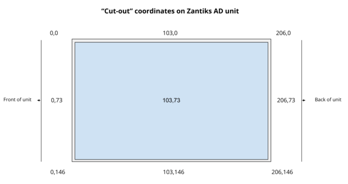
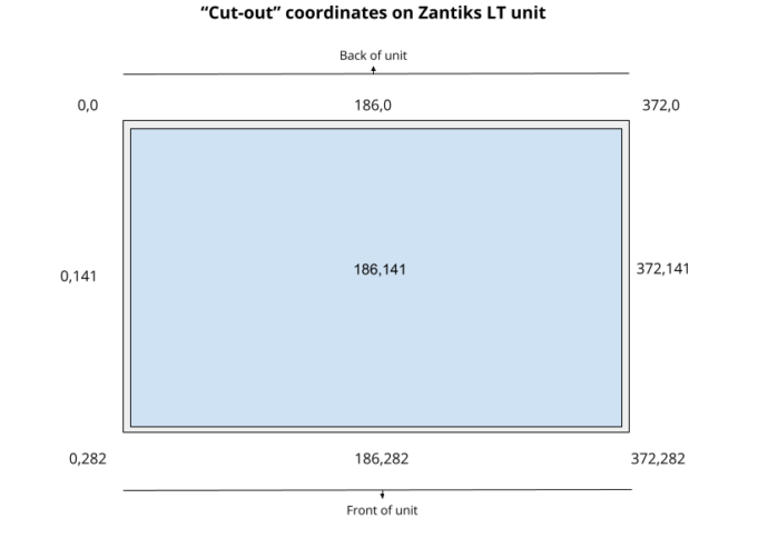
SETLIGHT
sets the type of visual stimulus to be displayed, as well as its location in the cutout. For ‘sprite’ images (.bmp) you can also set the size.
Examples:
SETLIGHT(LIGHT1,SQUARE,52,141,100)
SETLIGHT(LIGHT2,SQUARE,186,141,268)
SETLIGHT(LIGHT3,SPRITE,125,65,0)
SETLIGHT(LIGHT1,SQUARE,52,141,100) - sets LIGHT1 as a square shape of light with the centre of the square located at the coordinates 52,141 of the cut-out. The size of the square is set at 100 mm.
SETLIGHT(LIGHT2,SQUARE,186,141,268) - sets LIGHT2 to the size of the entire height of the screen display (268). The screen is centrally mounted and the active area does not reach the top and bottom of the cut-out / locator.
SETLIGHT(LIGHT3,SPRITE,125,65,0) - specifies that LIGHT3 is a 'sprite' bitmap image to be displayed on the cut-out coordinates 125,65 on the screen. The image's original size is used, as indicated by the final value 0. The size of the sprite can be altered by changing this number to the required size in mm.
The defined LIGHTs can then be controlled using the LIGHTS command (see below).
VIDEO
starts the video recording for a time (in seconds) specified in the brackets, saving the video with the name detailed in the apostrophes, “ ”
Example:
DEFINE WAIT_TIME 16

ACTION EXAMPLE

 VIDEO(15,"videotest")
 WAIT(WAIT_TIME)

COMPLETE
VIDEO(15,”videotest”) - records 15 seconds of video and saves the file into the Media Directory with a name starting “videotest” (the time and date will follow this label). The video recording has been designed to provide a useful record of short parts of the experiment, for reference only. The system prioritises running the experiment and processing the results live. It then will try and make the requested video. This means that one may have dropped frames, and it is possible the overlay of the screen onto the camera image can have a minor time delay over time. The time written into the video image will be correct (i.e., the computer time at which the image was acquired from the camera).
As the computer records the experiment the video images are processed later on and combined with any asset images used. This can lead to a slight ‘drift’ between these two events.
The “videotest” footage can be found in the Media Directory, accessible from a link on the Home page.
VIDEOSKIP
allows timelapse videos to be captured. It tells the systems to 'skip' the number of frames indicated in the parenthesis. By skipping frames, fast timelapse videos across the entire experiment can be created.
Example:
VIDEOSKIP(9)
VIDEOSKIP(9) records every 10th frame and saves the .avi file into the Media Directory.
VIDEOSTOP
stops the video before it has run the full time it has been programmed to run. This command is useful when the timings of an experiment can be adjusted using a DEFINE directive for the video length. You can stop a video without the need to calculate and adjust the video length each time.
Example:
VIDEO(30,"video_1")
WAIT(10)

VIDEOSTOP()
VIDEO(30,”video_1”) - sets the video to start to record a 30 second video
VIDEOSTOP() - stops the recording early after 10 seconds
See the Creating video files demo page for more details on the various video commands.
WAIT
details a time, in seconds, for the script to 'stay'. You can DEFINE the number of seconds in a previous DEFINE command.
Example:
DEFINE WAIT_TIME 10

ACTION EXAMPLE

 WAIT(10)
 LIGHTS(LIGHT1,ON)
 WAIT(WAIT_TIME)
 LIGHTS(ALL,OFF)

COMPLETE
WAIT(10) - will wait 10 seconds before moving on.
WAIT(WAIT_TIME) - will wait for 10 seconds if a DEFINE directive is stated: DEFINE WAIT_TIME 10
ZCOMMAND, synonym MOTORCOMMAND
controls the stepper motor that rotates the peristaltic pump, the feeder mechanism for powdered food and pellets, and the vibration of the MWP system. See the ZCOMMAND demo page for more details.
Examples:
ACTION EXAMPLE

 ZCOMMAND("U0 D1000 M200)
 WAIT(WAIT_TIME)
 ZCOMMAND("U0 D2000 M1 M-1 M1 M-1 M1 M-1 M1 M-1 M1 M-1 M1 M-1")
 WAIT(WAIT_TIME)
 ZCOMMAND("U0 D2000 M1 M-1")
 WAIT(WAIT_TIME)

COMPLETE
ZCOMMAND(“U0 D1000 M200”) - the numbers in the brackets and written between inverted commas “” indicate the rotation parameters:
'M' Number of Motor steps (e.g., 200, -50). 200 steps is a full 360 degree rotation
'D' Delay between motor steps, which sets the motor speed. This should not be below 1000 for 'free' motors (e.g. as used in feeders for the AD & LT). In the MWP the motor is mounted to cause vibrations, and not rotate, and so this limit does not apply).
'U' Step mode (0-3, for full/half/quarter/eighth step modes)
'P' (Pause) - sets a delay between actions in milliseconds (i.e., 'P50' will pause for 50 milliseconds)
VARIABLES
Variables are terms/numbers that are used as placeholders for values. Variables are used when these values need to be updated throughout the running of the script.
Zanscript can set values to variables both directly and as the result of processing by a command (i.e., conditional commands). Boolean variables, variables which contain only two possible conditions (i.e., true or false), can also be used.
Variables
Zanscript, by default, has variables @0-@899 available for use by the script. Users can create variables by setting a name to replace the variable number (e.g., DEFINE VARIABLE_TERM 100) or by using the variable number itself (e.g., @100=1). When assigning a variable name you need to DEFINE the variable at the top of the script. When using the variable number only, you do not need to DEFINE the variable. We recommend setting variable names for ease of reading your scripts.
- Variables, by default, are set to 0.
- Values are assigned to variables using an equal sign (e.g., @100=1; @variable_name=4).
- A variable is referenced in the script with the @ symbol in front of the variable name or number. Each time the variable is referenced in the script, it produces the value currently assigned to it.
- Boolean variables can be represented using integer values, where 0 equals false and 1 equals true. For these you can used both the numbers for the words.
Examples:
@101=3

INVOKE(SAMPLE,@101)
- @101=3 gives the variable @101 the value of 3. The action 'SAMPLE' is then invoked 3 times.
DEFINE CORRECT_RESPONSE 100


ACTION ANIMAL_RESPONDED

@CORRECT_RESPONSE=TRUE

    IF @CORRECT_RESPONSE=TRUE
        FEEDER(1)
    ENDIF

COMPLETE
- DEFINE CORRECT_RESPONSE allows you to use the term CORRECT_RESPONSE in place of the variable number 100. In the action, the variable is assigned to TRUE. Then, the IF...ENDIF statement is stating if @CORRECT_RESPONSE is set to TRUE, then turn the feeder on.
DEFINE STIM_RESPONSE 102
DEFINE TOT_NUM_STIM_OMISSIONS 103

@TOT_NUM_STIM_OMISSIONS=0

ACTION ANIMAL_RESPONDED

@STIM_RESPONSE=TRUE

    IF @STIM_RESPONSE=FALSE
        @TOT_NUM_STIM_OMISSIONS = @TOT_NUM_STIM_OMISSIONS +1
    ENDIF

COMPLETE
- DEFINE STIM_RESPONSE allows you to use the term STIM_RESPONSE in place of the variable number 102 and the term TOT_NUM_STIM_OMISSIONS in place of the variable number 103. @TOT_NUM_STIM_OMISSIONS is then set to a numeral value of 0, which can then be updated across the script. The IF...ENDIF statement is stating that if @STIM_RESPONSE is set to FALSE, then add 1 to the variable @TOT_NUM_STIM_OMISSIONS. Since it was assigned to TRUE, the omissions will not have a 1 added to it.

