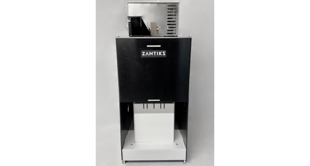
The Zantiks AD helps standardise behavioural experiments in animal models, such as adult zebrafish and mice. To use the Zantiks AD unit you need a small space on your lab bench, a nearby power supply, and your own browser-enabled device (e.g., smartphone/tablet/ laptop/PC/ Mac).
Zantiks AD kit
- Integrated unit (approx. 500mm H; 300mm D; 220mm W) with:
- Computer
- Camera
- Motor (to drive solid, liquid and gas delivery)
- Overhead 'house lights'
- Screen at the bottom of the chamber
- Power inputs to enable the addition of more built-in stimuli (e.g., mild electric shock)
- Zanscript (Zantiks software)
- 12V power cable
- Zantiks router, power cable, and Ethernet cable
- A router is supplied with the first unit, this is typically a TP Link router with 4 LAN ports. The single WAN port is not used in the typical configuration and is taped over to stop it being used by mistake. Subsequent units can be networked to this router, using a network switch if necessary.
Add-on equipment for fish
The AD unit comes with some free add-on equipment for fish:
- One tank with mesh lid – approx. 150mm H; 200mm D; 140mm W and with clear bottom and opaque white sides
- Two stainless steel shocking plates with cable and testing LED strip - For use as a mild shocking stimulus in aquatic environments
- Controllable voltage and duration
- Brass feeder mechanism for solid food delivery - attaches to the motor
- Peristaltic pump unit for liquid delivery - attaches to the motor
- We recommend you use the following tubing with it: 2mm internal diameter, 4mm external diameter silicone tubing.
- External light with an extra connector
- Tank inserts to create multiple different arenas:
- Arena lengthwise dividing inserts x 3
- Arena widthwise dividing inserts x 3
- Food magazine insert x 1
- 5-aperture insert x 1
- Open base lengthwise inserts x 2
- Open base widthwise inserts x 2
- Light-dark inserts x 1
- Novel tank diving inserts x 1
- A pair of Y-Mazes
Add-on equipment for mice
The AD unit comes with some free add-on equipment for mice. New users should discuss their requirements as bespoke inserts could be made.
- One cage with lid - approx. 150mm H; 200mm D; 140mm W and with clear bottom and opaque white sides
- Pellet feeder mechanism for solid food delivery - attaches to the motor
- Peristaltic pump unit for liquid delivery - attaches to the motor
- We recommend you use the following tubing with it: 2mm internal diameter, 4mm external diameter silicone tubing.
- External light with an extra connector
- Cage inserts to create multiple different arenas:
- Food magazine insert x1
- 5-aperture insert x 1
- Two-choice insert x 1
Setting up the AD
- Place the AD unit on a stable surface close to a power socket and away from disturbance.
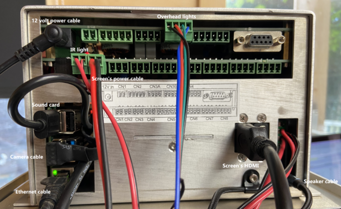
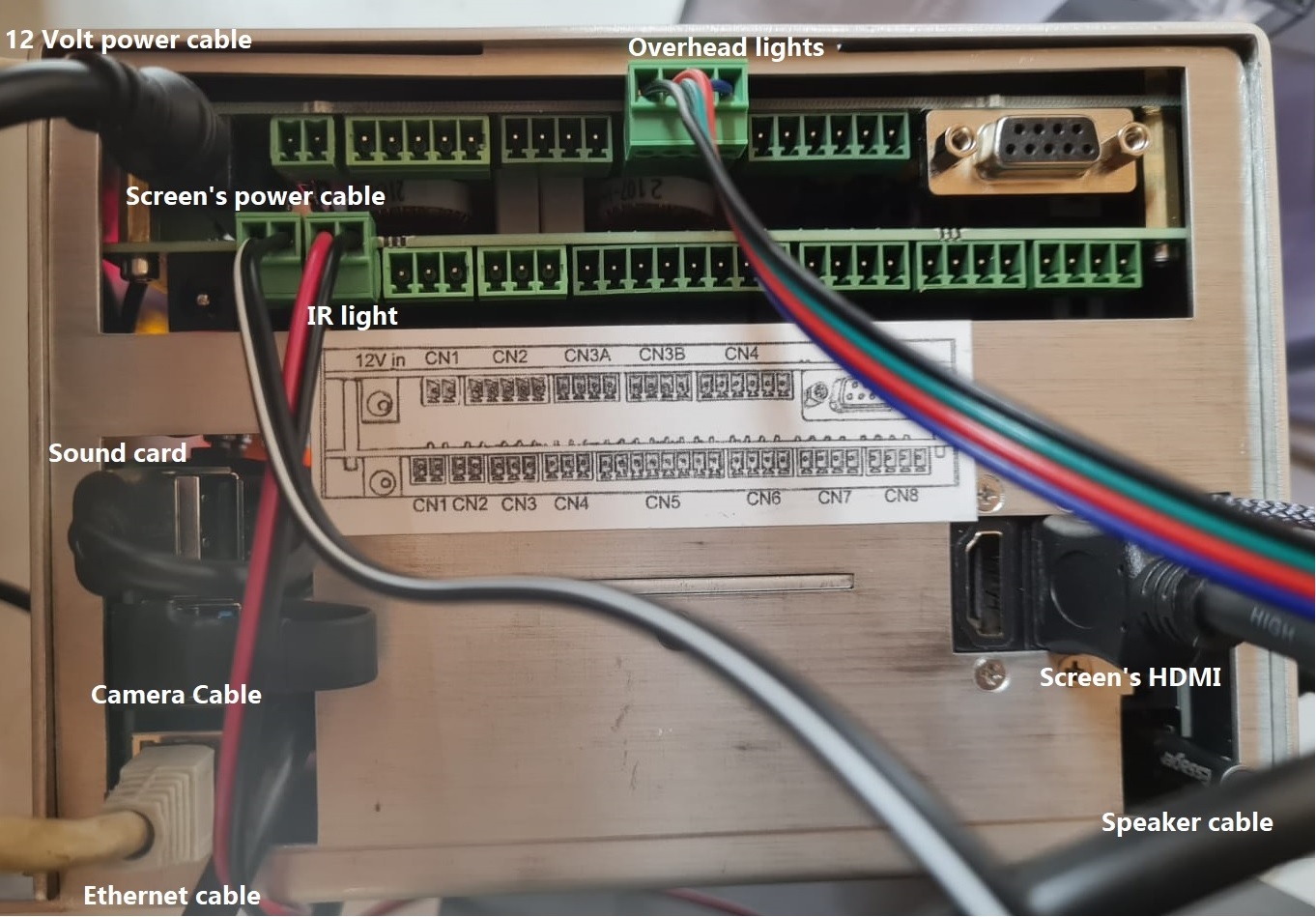
- Plug in the green connectors for the Infrared (IR), overhead lights and screen power into the side socket.
- Ensure all wires are connected to the green connection plugs securely. Please see the tutorial video on how to do this.
- Ensure all wires are connected to the green connection plugs securely. Please see the tutorial video on how to do this.
- Plug in the camera cable (the flat USB cable with the blue connector) and the sound card cable (the round cable), camera, and screen HDMI.
- Insert the 12V power supply cable into the upper left, back socket of the AD unit and plug it into the mains socket.
- Connect the ethernet cable at the back of the Zantiks unit and plug this into any of the 4 slots available in the LAN section of the router.
- NOTE: the blue WAN socket has been covered. This socket should not be used and has been covered to discourage users from trying to connect using the WAN rather than the 4 LAN sockets.
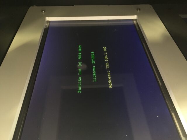
- Turn on the router. When the Zantiks unit is powered on, a text screen will load and scroll across the screen in the unit.
- The unit’s IP address will display on the screen each time the unit is turned on (see image below); it is also included on your delivery note. The IP address is used to identify the unit on the Zantiks Control Console.
- Using any browser-enabled device:
- Go to network settings and connect to the wifi network “Zantiks_XXX” (XXX being specific to your lab and written on the delivery note).
- Type in the network password, which is initially provided as: behaviour, simply (this is also included on your delivery note).
- Your computer will likely come back with "connected without internet". This is correct as it is just a local network, it does not provide internet access.
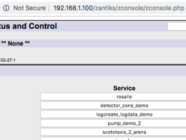
- Open a web browser of your choice, go to the address bar and type in the IP address for your Zantiks unit.
- The web browser should now display the Zantiks Control Console page (see image below).
Setting up the side screen
The AD unit comes with a built-in bottom screen and the option to buy a side screen for lateral presentation. The side screen can be used instead of the bottom screen. Both screens cannot be in use at the same time.
The side screen can sit at either the back or at the front of the chamber. A tank consisting of 3 black walls, a clear tank floor and 1 clear side wall (to place against the side screen) is supplied. A 2-choice insert comes as standard with a side screen.
1. Shutdown the unit and unplug the power supply when switching from the bottom screen to the side screen.
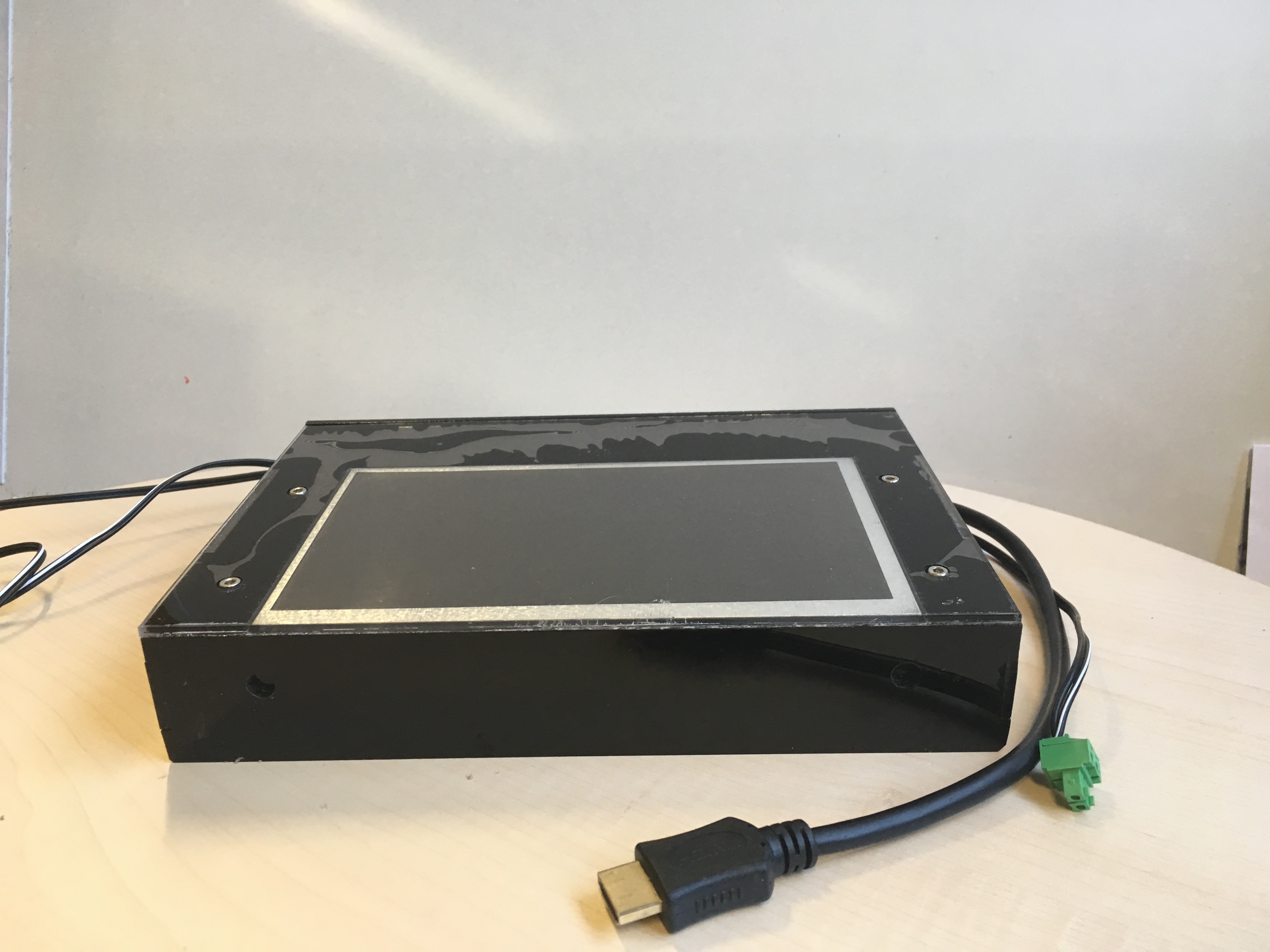
2. The side screen unit has 2 connections: an HDMI cable and a 2-way green, connector plug with 2-wire (black and white) cable. These are identical cables to the built-in screen.
NOTE: the 2 holes at the bottom of the side screen unit will be used to accurately locating the screen in the system.
3. Unplug the built-in screen's cables with care: the HDMI cable and a 2-way, green connector plug with 2-wire (black and white) cable which plugs into CN1 or CN2.
NOTE: the additional 2-way green, connector plug with the black and red 2-wire cable is for the infra-red lights located at the base of the unit.
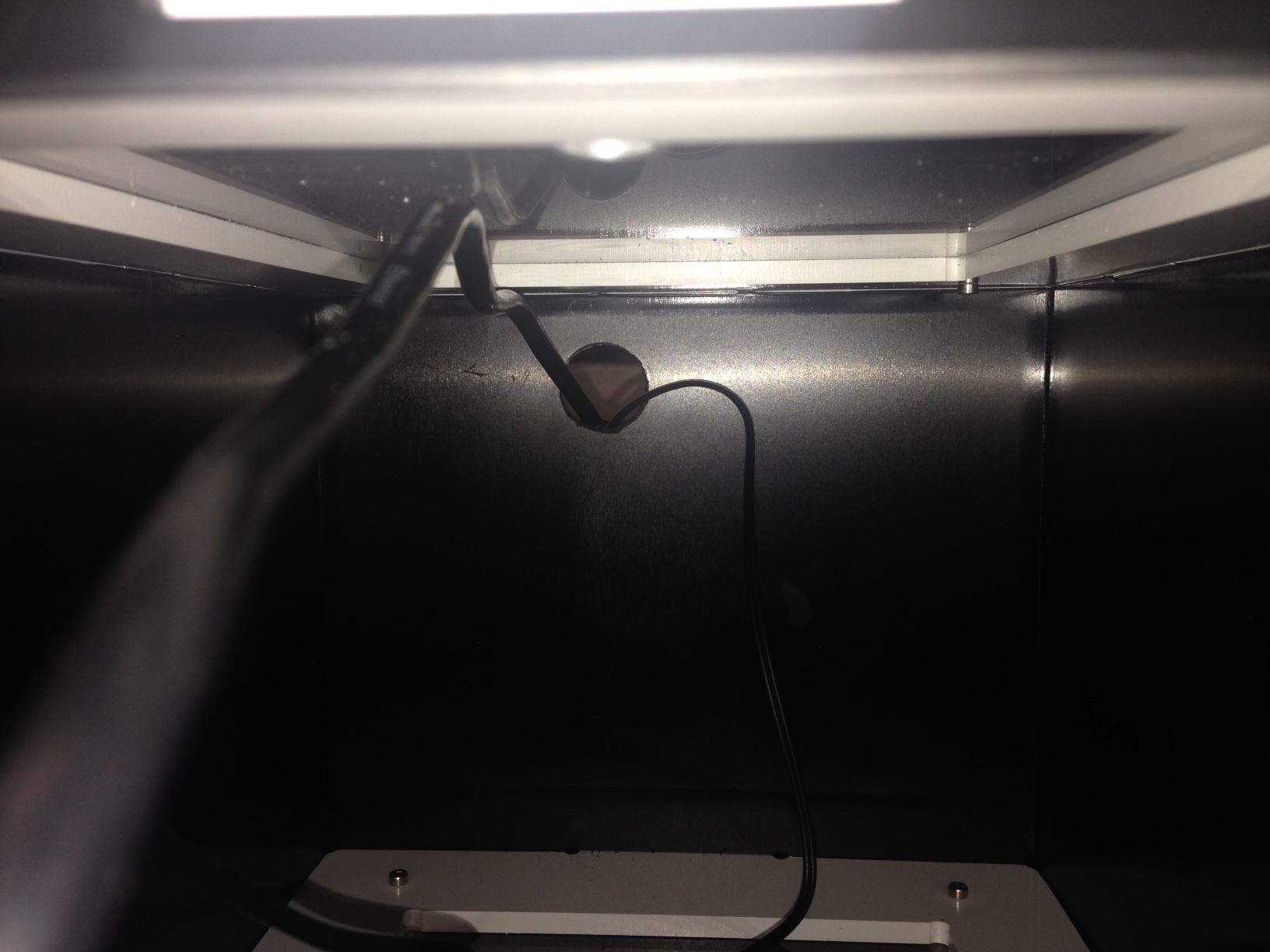
4. Thread the screen's 2 cables through the circular hole at the back of the unit
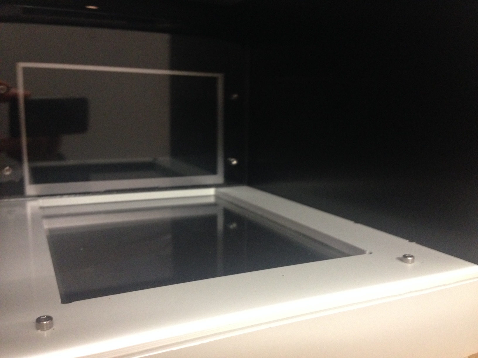
7. Slide the screen back until the cables are fully out of the unit and the side screen is flush against the back wall.
8. When the side screen is at the back of the unit the two screws that protrude up from the bottom screen should slot into the holes located under the side screen unit.
9. Once the side screen is in place, plug in the side screen cables, taking care to insert the HDMI cable in the slot found in the back of the top box, and the 2-way green, connector plug into CN1 (or CN2).
10. Re-connect the unit to the power supply.
How to use the side screen
The side screen has different dimensions to the bottom screen. The images on the side screen will appear elongated (the pixels are not square, but instead 1 x 0.7). Consequently you need to resize any images / bitmaps that you use so that the horizontal dimension is 0.7 of the original bitmap.
For details on writing a script and creating bitmap images for the side screen see the Side screen demo script webpage.
The external lights
An external light can be used with the side screen to illuminate the food magazine when reward is delivered.
The external light's 4-way connector plug slots into the back of the top box at CN7.
The external light hooks onto the top of the end of the tank, once the tank is in the chamber. Attach the external light to the tank after the tank/cage is placed in the chamber. The tank will not slide into the chamber with the external light attached.
To turn the light on within a script, use the code:
LIGHTS(LIGHT15,ON)
Next go to Calibrating your Zantiks unit to see how to calibrate the unit in order to generate tracking assets.

