- Zantiks MWP kit
- MWP Behavioural Studies
- Assembling the motor plate
- Setting up the MWP
- Assembling standard temperature control
- Assembling peltier temperature control
- Assembling the light stimulation plate
- Assembling the overhead light stimulation plate
- Assembling the side stand for cuvettes
- Changing the camera lens
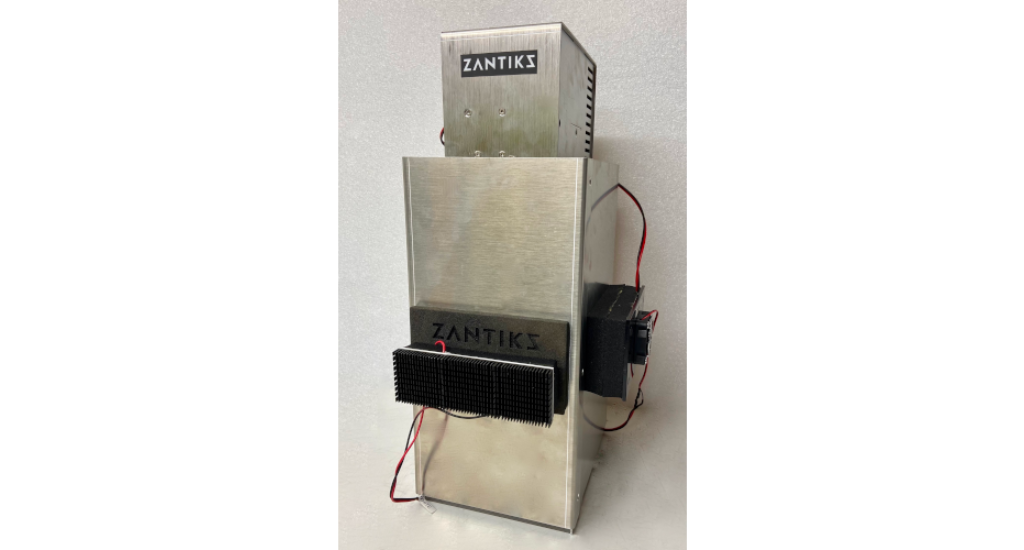
The Zantiks MWP unit helps standardise behavioural phenotyping in model organisms, such as larval zebrafish, Drosophila and Daphnia. To use the MWP unit you need a small space on your lab bench, a nearby power supply, and your own browser-enabled device (e.g., smartphone, tablet, laptop, PC, Mac).
PLEASE NOTE: If you purchased your MWP unit before March 2021 you will need to follow the instructions for our first generation (Z1) unit which can be found here.
Zantiks MWP Z2 kit
- MWP chassis and standard top box. Integrated with:
- Zanscript (Zantiks proprietary scripting software)
- Built-in features / stimuli
- overhead 'house lights'
- vibration motor plate
- camera; 4mm lens
- computer
- A 12V power cable
- Zantiks router, power cable, and Ethernet cable
- A router is supplied with the first unit, this is typically a TP Link router with 4 LAN ports. The single WAN port is not used in the typical configuration and is taped over to stop it being used by mistake. Subsequent units can be networked to this router, using a network switch if necessary.
- Light stand with diffuser to hold a multi-well plate or Petri dish and your choice of LED wavelength.
- A standard temperature control system
- NOTE: a peltier temperature control system is offered as an optional add on if required.
Behavioural studies in the MWP include:
- Locomotor activity
- Circadian rhythm monitoring
- Toxicity, phenotyping and drug screening
- Startle response, habituation and prepulse inhibition
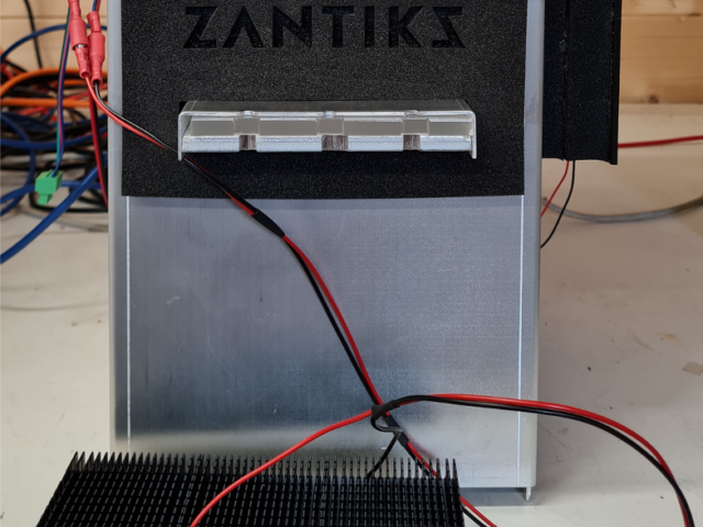
Assembling the motor plate
When assembling the MWP unit, the motor plate needs to be inserted before plugging in the mains power. The motor plate is delivered detached in order to prevent breakage during transit.
The video below shows how to open the front section of the MWP unit so that the motor plate can be inserted and attached. To do this, a T10 Torx driver, or similar, is necessary (not an allen key). This tool should be included with the unit.
How to assemble the motor plate to the MWP unit
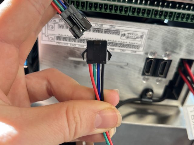
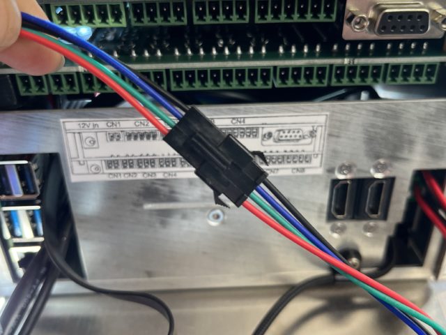
Connect the motor plate via the push plugs shown in the images below. There is only one way around that the push plugs fit and should connect without any force. It is important that the motor plate is connected before supplying power to the MWP system. Additionally, if you need to disconnect the motor plate for any reason ensure that the system has both been shut down & unplugged from the mains power before doing so.
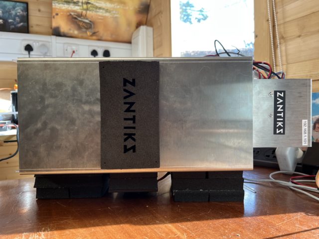
Setting up the MWP
- Place the MWP unit on a stable surface close to a power socket and away from disturbances.
- Insert the 12V power supply cable into the top left side socket of the MWP and plug into the mains.
- Connect the ethernet cable at the side of the MWP unit, just below the 12V power cable, and plug this into any of the 4 slots available in the LAN section of the router. Note that the blue WAN socket has been covered. This socket should not be used and has been covered to discourage users from trying to connect using the WAN rather than the 4 LAN sockets.
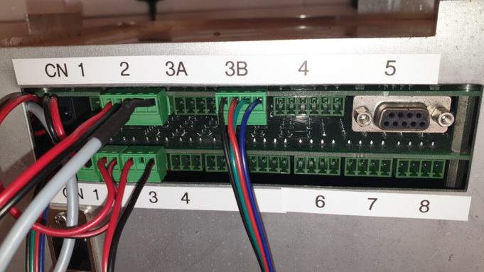
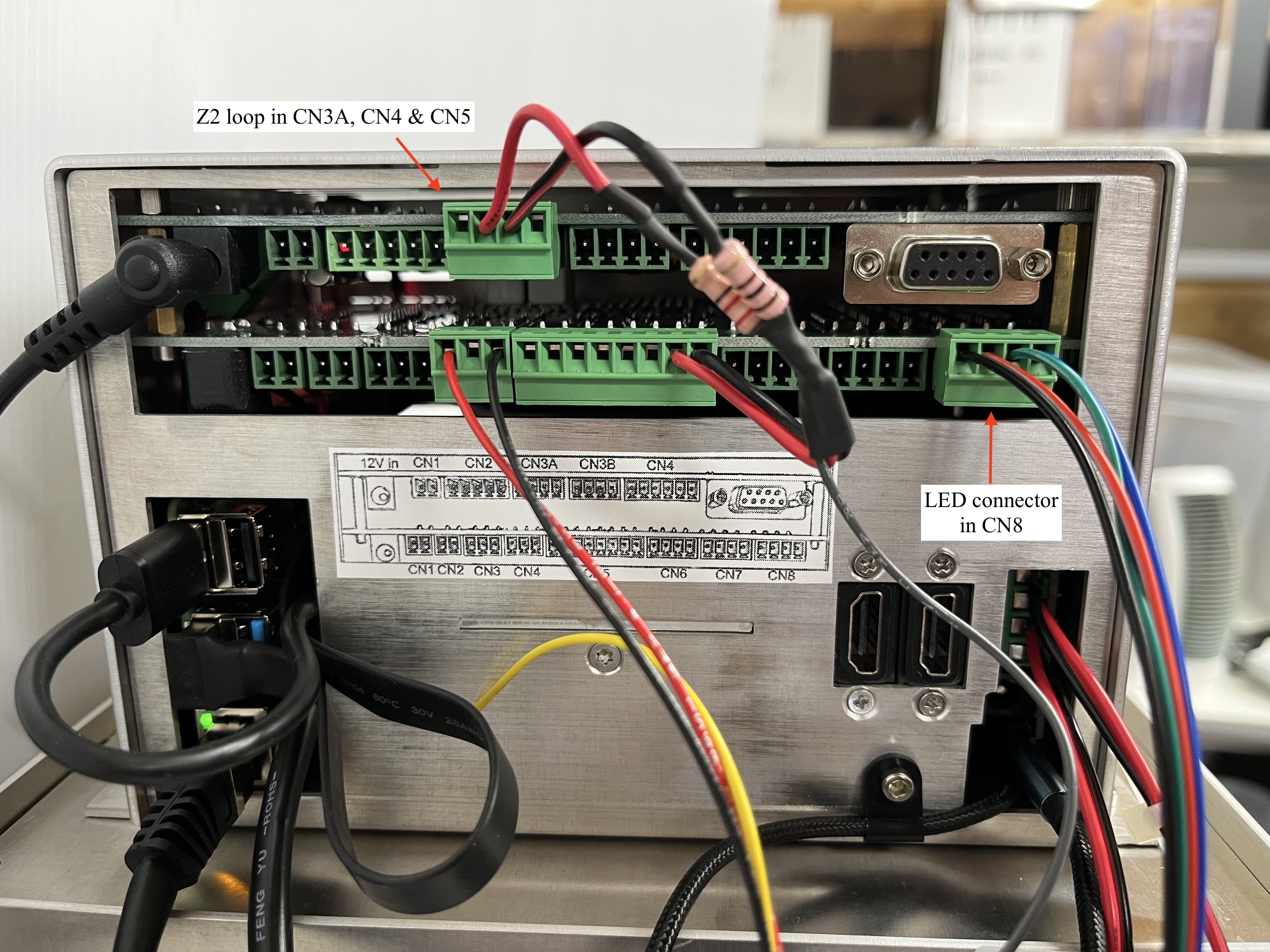
- Connect the rest of the MWP top box cables as shown in the diagram below.
- Ensure all wires are connected to the green connection plugs securely. Please see the tutorial video on how to do this.
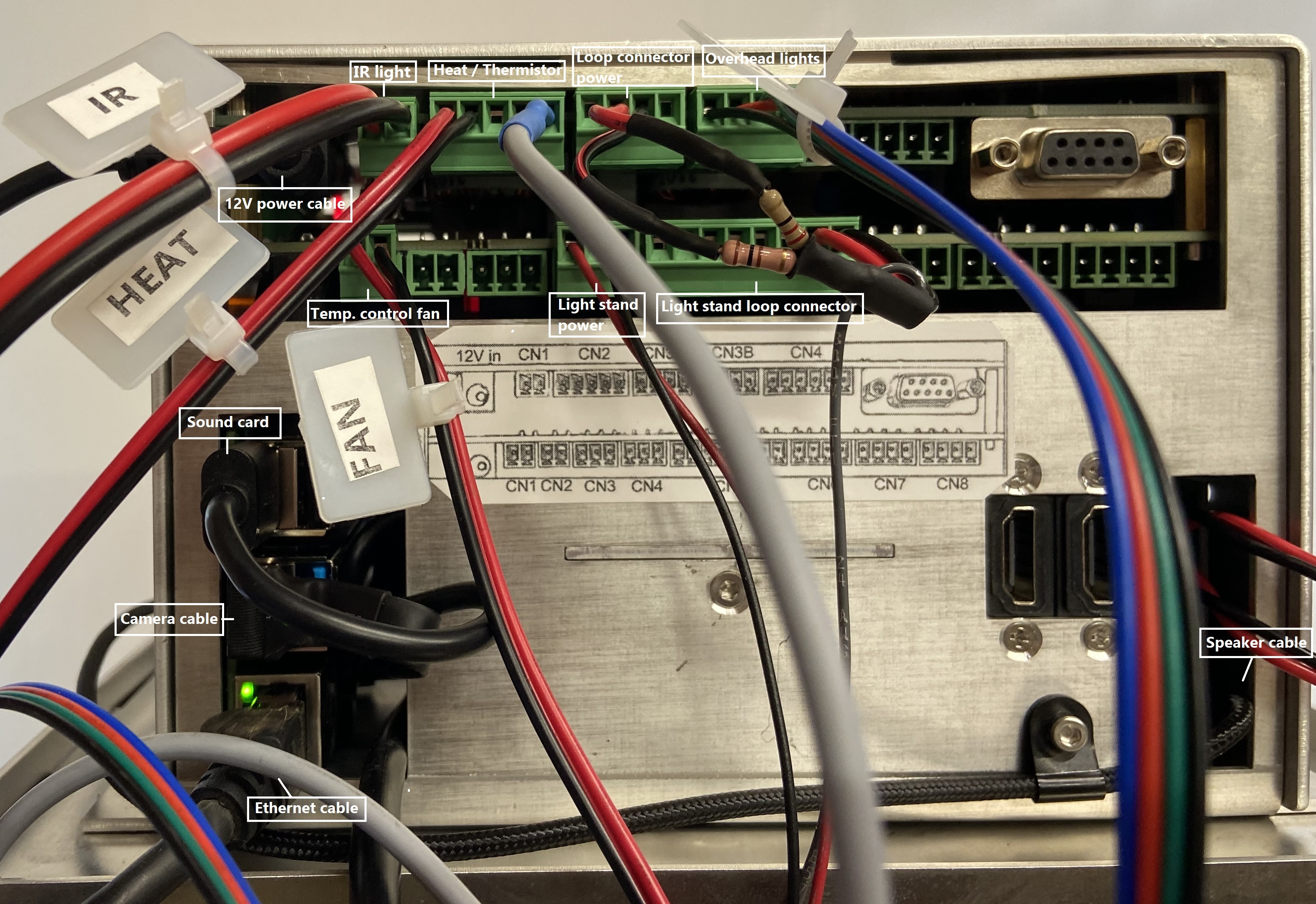
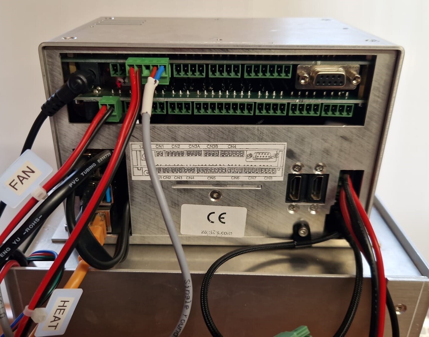
Zantiks Z2S top box: the unit's 12V power supply is in the top left; below this is the sound card (round cable) and camera cables (flat USB cable with the blue connector); directly below these is the ethernet cable. On the lower right is the speaker's cable. CN1 on the upper board houses the IR light's wire, CN2 on the upper board is the heater and thermistor's cables. CN3A is the light stand loop connector's power cable & CN3B houses the overhead lights cable; CN1 on the lower board houses the power supply for the temperature control unit's fan. CN4 and CN5 on the lower board are the light stand's power supply and the loop connector for the LEDs, respectively.
- Turn on the router and the mains power to the Zantiks unit. Wait a few minutes for the MWP unit to power on.
- If you have only one Zantiks unit, the address will be 192.168.1.101. The IP address is used to identify the unit on the Zantiks Control Console. The top box should be labelled with the IP address and the licence number. (The IP address is also included on your delivery note).
- Using any browser-enabled device:
- Go to your device’s network settings and connect to the wifi network “Zantiks_XXX” (XXX being specific to your lab and written on the delivery note).
- Type in the network password, which is initially provided as: behaviour, simply (this is also included on the delivery note).
- Your computer will likely come back with "connected without internet". This is correct since it is just a local network, it does not provide internet access.
- Open a web browser of your choice, go to the address bar and type in the IP address for the Zantiks unit.
- The web browser should now display the Zantiks Control Console page.
Standard Temperature Control - Assembly Instructions
This system is comprised of two components which moves ambient air through the unit. If/when required, the air can be heated to achieve a temperature above ambient room temperature by up to 10°C.
Components include:
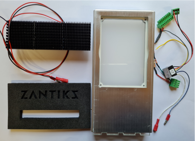
- 1 x Temperature control heater
- 1 x Cover plate
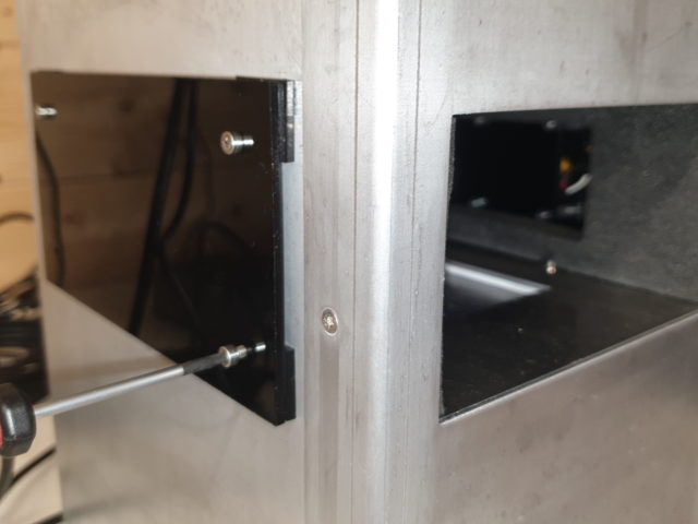
The 2 components are screwed to the sides of the MWP unit, the temperature control heater is attached to the right hand side of the unit using the four 55mm M3 screws provided. The white cover plate is attached to the left hand side using the 18mm M3 screws provided.
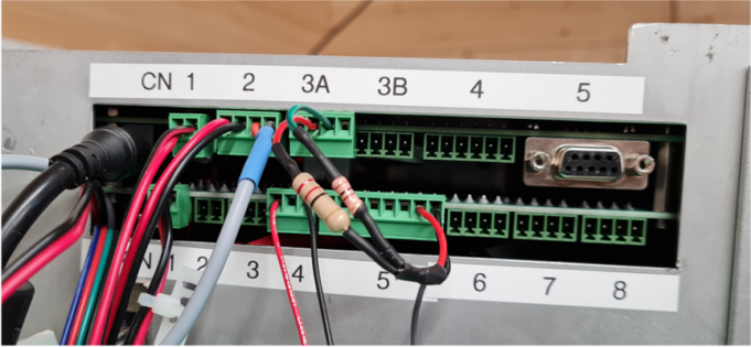
There are 2 pairs of wires that come out of the standard temperature control heater. These are labelled FAN (with a 2 way green connector attached) and HEAT (with bare wires).
- The FAN lead should be plugged into the upper or lower CN1.
- The wires labelled HEAT should be attached to the 5-way plug which already has the grey thermometer wire attached. The HEAT wires are screwed into the outer 2 holes of the connector, opposite the thermometer. The red cable attaches to the outside hole and the black cable goes in the inside hole. This is then connected to CN2 on the upper board.
Please compare your set up with the image below to ensure you have wired your temperature control system correctly.
Standard Temperature Control - script command
SET(THERMOSTAT,28)
SET(THERMOSTAT,#) can be used in a Zanscript to set the temperature (in Celsius) of the experimental environment.
Please refer to the Temperature control demo MWP page in the support section of the website for more detailed information on how to operate the temperature control unit.
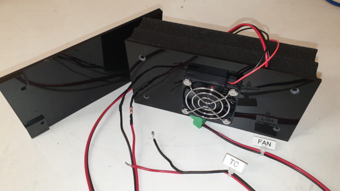
Peltier Temperature Control - Assembly Instructions
NOTE: the Peltier temperature control system is an optional add-on.
This system is comprised of 7 components including:
- 1 x Temperature control (TC) unit box
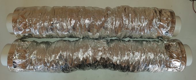
- 2 x Insulated ducts
- 4 x insulated connector collars
The TC unit box blows air, and can insert or remove heat from it (to raise or lower temperature above or below room temperature, as required). The air is then moved to the MWP unit via an insulated duct, and returned to the TC unit via another insulated duct, all of which are connected by insulated connector collars. The TC unit is powered directly from the MWP unit itself.
NOTE: If you have one of the older design Peltier units, see the video for assembly here.
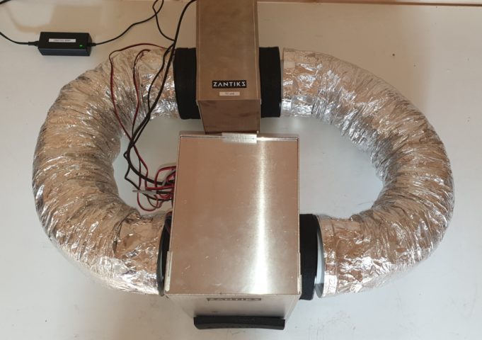
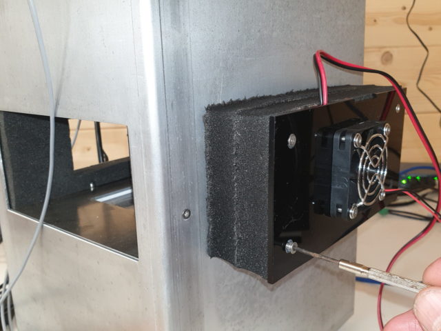
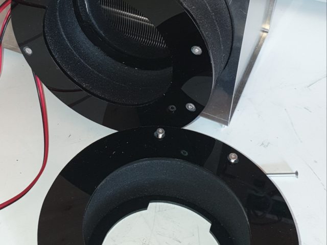
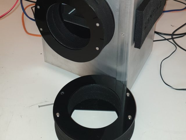
Insulated connector collars need to be attached on both sides of the MWP unit, and the TC unit. Please note they are different. The MWP collars have a rectangular cut out panel which lines up with the open panels on the sides of the MWP unit. The TC collars have circular cut outs and should be oriented as shown in the image below with the straight edge facing upwards.
The collars are attached using the 50mm countersunk screws. The connector may need to be compressed slightly to allow the screw thread in.
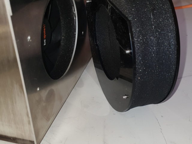
The insulated ducts may then be used to connect the TC unit to the MWP unit by slotting them into the collars.
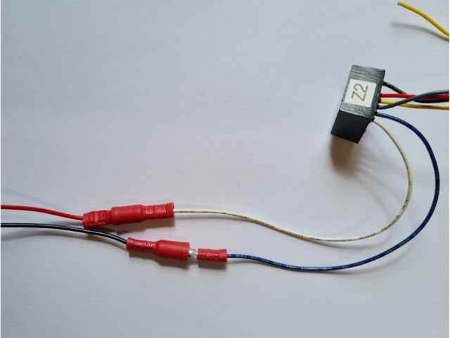
There are 2 pairs of wires that come out of the side of the TC unit.
One pair is already attached to a 3-way plug. This powers the fans, and should be plugged into CN3 on the lower layer of connectors in the MWP. The other pair is delivered as bare wire, and it should be connected to the 5 way connector already present as part of the MWP. This is plugged into CN2 on the upper layer, and has the hermistor attached (a round grey wire). Please see the picture below to see how the wires should be connected. The red wire from the TC unit should be at the left outer edge of the connector, and the black wire next to it.
Peltier Temperature Control - script command
SET(TCS_MODE,PELTIER)
SET(THERMOSTAT,28)
SET(TCS_MODE,PELTIER) - allows for control of the peltier unit. This command is necessary for the software to recognise the Peltier Temperature Control unit, as the default control mode is the 'Standard Temperature Control'.
SET(THERMOSTAT,#) can be used in a Zanscript to set the temperature (in Celsius) of the experimental environment.
Please refer to the Temperature control demo MWP page in the support section of the website for more detailed information on how to operate the temperature control unit.
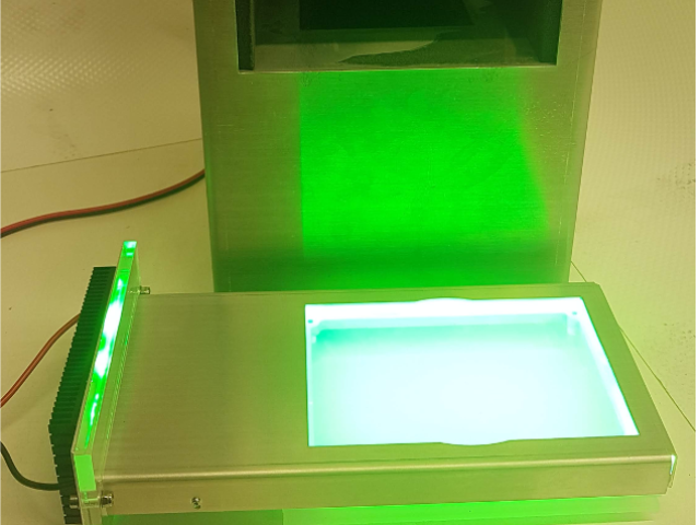
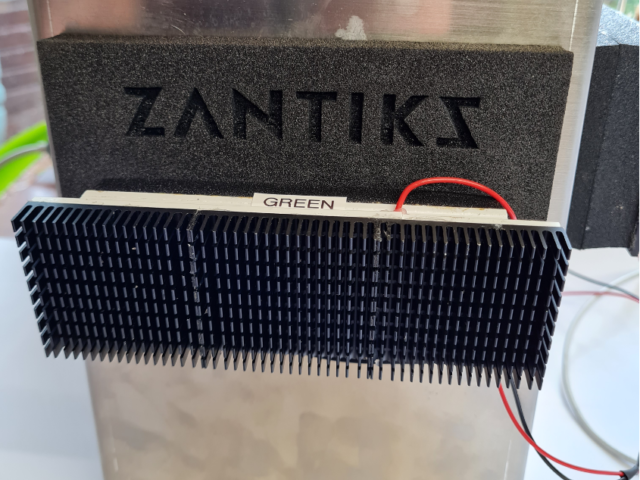
Assembling the Light Stimulation plate
The main components of the Z2 light stimulation plate include:
- Light stimulation plate with incorporated diffuser
- LED holder (with choice of wavelength lights)
- Control circuit (Z2 loop) to plug directly into the MWP unit
- Foam door (with hole for light plate)
The system plugs directly into the MWP and does not require an additional power supply.
Control of the system is from the included Zanscript programming language and incorporates control of both the brightness of the light and the duration of the stimulus.
The brightness of the light is controlled by the voltage set on Output4. This is the 7th connector on the 8-way output located at CN5 of the lower board. This can be overridden by other controls.
The LED holder is connected to the control circuitry with the push connectors. The LED holder can then be attached to the light plate and inserted into the MWP unit with the foam door to prevent any excess light entering or exiting the unit.
Please refer to the Light Stand Demo MWP page in the support section of the website for more detailed information on how to operate the light stand.
Assembling the Overhead Light Stimulation plate
The overhead light stimulation plate can be used in a number of ways/situations:
- To provide light of a specific wavelength from above the organism rather than below (as it is in the standard setup)
- To provide more/brighter lighting of a specific wavelength by transmitting both from above and below the organisms
- To alternate between two specific wavelengths within a single experiment using one wavelength above the organism and a second wavelength below.
NOTE: If you are just using a single light source from above, you can use the existing LED lights which come as standard with the MWP for the light stimulation plate. If you will be using the system to provide light from both above and below, you will need to purchase additional LEDs.
The main components of the overhead light stimulation plate include:
- Overhead light stimulation plate
- LED holder (at the wavelength of your choice)
- Foam door (with two holes for overhead and standard light stimulation plate)
- Connector cable with 4-way green connector and LED push plugs, or Z2 loop
The LEDs for the overhead light stimulation plate plug directly into the MWP and does not require any additional power supply. Control of the lights is from the included Zanscript programming language and incorporates control of both the brightness of the light and the duration of the stimulus.
Assembly tutorial for the overhead light stimulation plate
There are multiple options for connecting the LEDs to the top box.
1. Connect the overhead LEDs alone with either the Z2 loop or with the 4-way connector cable which can be used in either CN7 or CN8 to provide dimmer light.
2. Connect both the overhead LEDs and a second set of LEDs from below using the Z2 loop for one of the LEDs and a 4-way connector cable in CN7 or CN8 for the other set of LEDs.
NOTE: connecting the LEDs to CN7 or CN8 provides a dimmer light than connection with the Z2 loop.
3. Connect both the the overhead LEDs and a second set of LEDs from below using two 4-way connector cables one plugged into CN7 and another into CN8.
NOTE: This setup will mean that both of the LEDs are dimmer than what can be achieved with the Z2 loop and will require and additional 4-way connector.
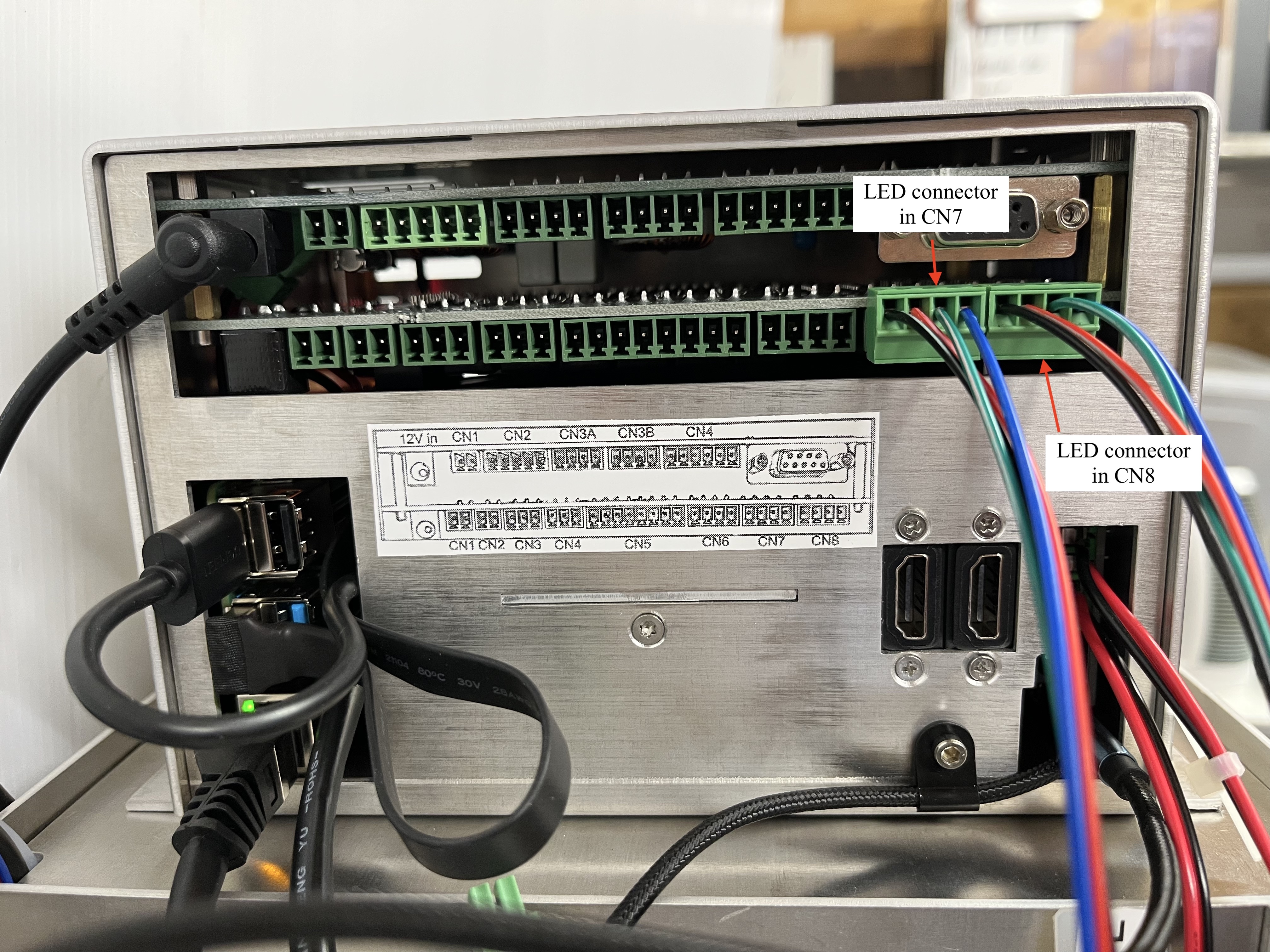
WARNING: if using the 4-way connector cable to power one or both LEDs you must only plug them into CN7 or CN8. If plugged incorrectly into another port, you can permanently damage the systems ZCB board.
To operate the LEDs in Zanscript; You can use the same coding for the light stimulation plate when using the Z2 loop which can be found in the light simulation demo MWP. When using the 4-way connector cable in CN7 or CN8 you will require a different code which can also be found within the light stimulation demo page.
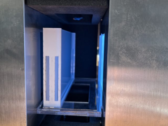
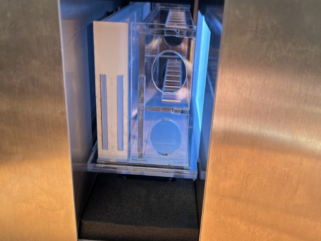
Assembling the Side Stand for Cuvettes
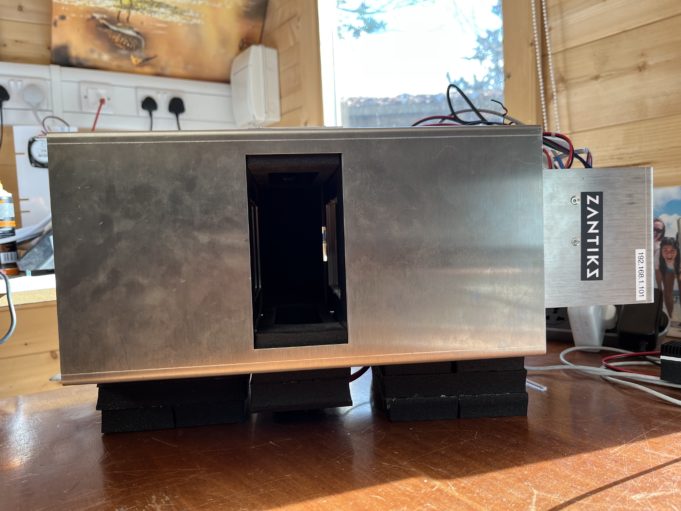
All of the Zantiks systems can provide a side view by simply rotating the system onto its side. Here we will describe how to set up the side view stand for cuvettes in the MWP:
1. Rotate the MWP system onto its side with the standard temp control facing downwards. Two foam supports are supplied to help raise the MWP to allow space for the temperature control.
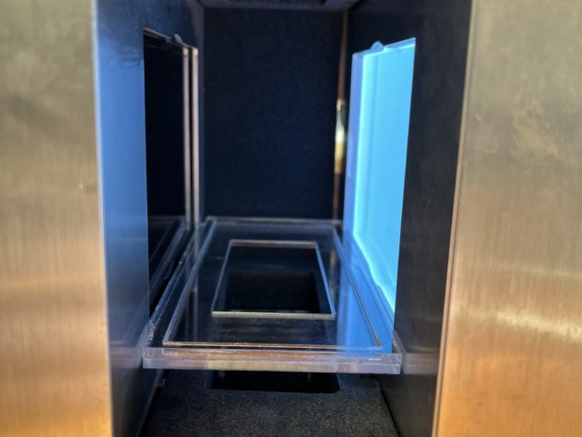
2. Place the locator plate within the observation chamber of the MWP. It will fit between the left and right side of the chamber (top and bottom when the system is standing upright) and will hold the cuvette stand within the camera view.
3. Place the diffuser plate on the locator plate and to the left (the bottom when the system is standing upright).
4. Place the loaded cuvette stand on the locator plate to the right of the diffuser.
5. Cover with a foam door
Once the side view stand for cuvettes has been assembled correctly into the MWP system you can build the arenas and zones asset. See the asset building manual for the MWP for instructions on asset building and for the script download.
Changing the camera lens
When higher magnification is required, for example measuring zebrafish embryo activity, the standard 4mm camera lens can be exchanged for the supplied 12mm lens.
Activity analysis of 24hpf zebrafish embryos exposed to a sedative and a stimulant under the 12mm lens
How to change the camera lens is explained in detail in the video tutorial below.
The 12mm lens should arrive already focussed and ready to use. However, if the lens has shifted out of focus during transit. Please refer to the refocussing the camera manual.
Swapping between the standard and high magnification camera lens tutorial
Next, go to the manual Calibrating you Zantiks unit, to see how to calibrate the unit in order to generate tracking assets.

