The LT unit is dispatched in 3 sections and needs to be assembled. The video demonstrates how to assemble the unit, the LT component list and full written instructions are below. There are also links the support articles that will help familiarise yourself with the LT unit.
How to assemble the LT unit
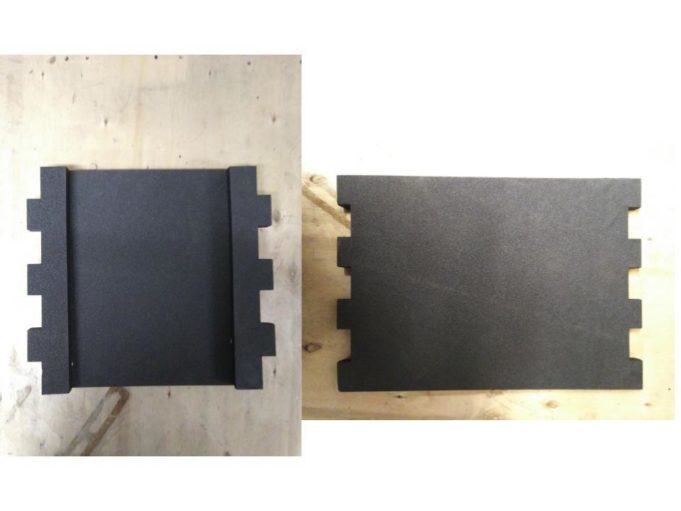
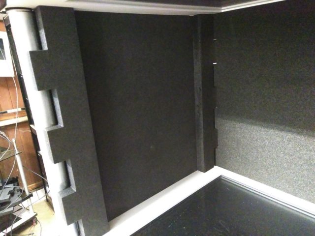
The sides of the experimental chamber
Once you have assembled the LT unit you can slot on the foam sides to create an isolated chamber.
You will have 2 different types of foam side and these slot in between the four posts surrounding the chamber.
LT unit components:
Main unit:
- LT top box ( + 4 6mm 3M screws)
- Top plate (with attached motor plate)
- Mid plate
- Base plate (with attached screen)
- 4 400mm rods with pre-attached nut
- 4 280mm rods with pre-attached nut
- 8 315mm pipes
- 4 nuts
- 8 washers
- 8 dome nuts
- 4 long foam panels
- 4 short foam panels
Tools:
- 3M allen key
- 19mm spanners
- Assorted electronics:
- Top box power pack
- CISCO Router
- CISCO router power pack
- Network ethernet cable x 2
- Main screen power pack
- HDMI lead
Possible add ons:
- Tanks (full size, narrow, etc.)
- Opaque tank inserts (+ holding tabs)
- Motor ( + 2 6mm 3M screws)
- Thin metal feeder tube (335mm)
- Brass feeder mechanism
- Peristaltic pump (+ piping)
- Shocking set
- 3D tracking set
- Side screen (+ power pack + HDMI)
Assembly of the LT unit
All parts need to be screwed relatively tightly unless stated otherwise. We recommend that you screw the parts together gently initially, tightening each four sides a bit at a time using the spanner/ allen key supplied, until they are firmly secured.
- Take the base plate (with screen) and turn it upside down so that the back of the screen is facing you. Screw a dome nut onto each corner. These need to be screwed on most of the way and can be adjusted to make the unit level.
- Turn the base plate the correct way round on its new feet. Take the shorter rods and screw them into the nuts on the base plate. These need to be screwed in as far as they’ll go. It doesn’t matter which orientation the rods are screwed in.
- Slide a pipe over each of these new rods so that they cover the long nuts coming out of the base plate.
- Take the mid plate so the black side faces up and the white side faces down. Place it on top of the rods so that the wires coming from its side are on the same side as the wires coming from the base plate. Then screw in. As the nut on top of the mid plate turns, so will the lower one. Continue until you can’t anymore.
- Take the longer rods and screw then into the mid plate. Again it doesn’t matter the orientation of the rods.
- Slide a pipe over each of the rods so it covers the nuts on the top of the mid plate.
- Slide a washer down of each rod so that it sits on top of the pipe. Arrange it so that the curved side is facing down and the flat side is facing up.
- Take the top plate and place it on the rods so that the feeder hole is in line with the one on the mid plate so that the motor plate is on the top of the unit and the side without the wires. This will arrange it so that the side with many smaller holes is closer to the side of the unit that the wires come out of.
- Slide another washer onto each rod now with the flat side of it facing down.
- Screw a nut down each rod to secure the top plate in place.
- Screw dome nuts onto the top of each rod.
- Take the top box and place it on the top plate so that the inputs are facing the side with the wires and the plastic washers on the bottom of the top box fit into the holes drilled in the top plate. Screw down with 4 of the 6mm 3M screws provided, using the allen key, until secure.
Support
We are currently creating a specific manual for the LT, which will replace the outline and introduction above, and also other support material such as demo scripts and tutorials for the LT unit.
Set up instructions
Manuals
There are some manuals that are applicable to all Zantiks units. These can be found in the online manual section:
Demo scripts
There are a few demo scripts for the AD unit and for Zanscript which will be useful, in particular:
- Feeder demo - this also illustrates how to move the motor on the motor platform so that you can either have it set for the brass feeder mechanism or for the peristaltic pump.
- Peristaltic pump demo
- Locomotor data demo
- Screen colours demo
Tutorials for Zanscript
The Tutorials for Zanscript are helpful introductions, with videos, explaining how to write and edit scripts using the Zantiks proprietary software, Zanscript.
As a new user please let us know what experiments you want to conduct in the unit and we will help write the scripts.
Protocols which use the LT unit
There are a few protocols that are relevant to the LT unit:
- Y-maze
- Light dark transition test for mice
- Pavlovian avoidance learning with zebrafish, using the AD tank

