This page will run through how to set up the RGB UV LEDs for the Zantiks MWP system; how to set the power/brightness of the individual wavelengths; and how to operate the lights in Zanscript proprietary software.
RGB UV LED kit
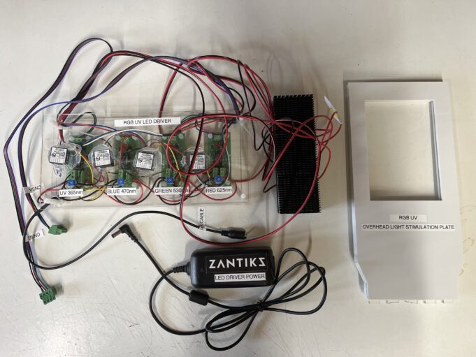
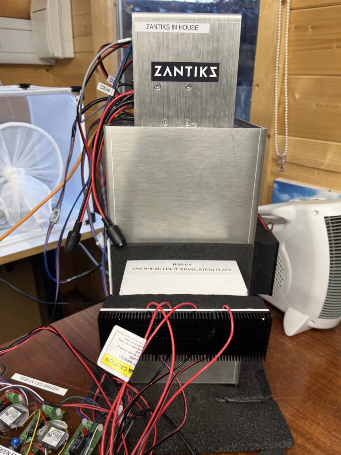
The RGB UV LED is an LED holder which contains an LED for red (625nm), green (530nm), blue (470nm) and UV (365nm) wavelengths. The individual LEDs are controlled by a driver. The driver will need to be powered by an external power source and is controlled by the Zantiks software by plugging into the top box. The light is displayed evenly across a light stimulation plate which is placed above the test organism. The equipment for the set up (excluding the foam door) is shown in the image below.
Set up
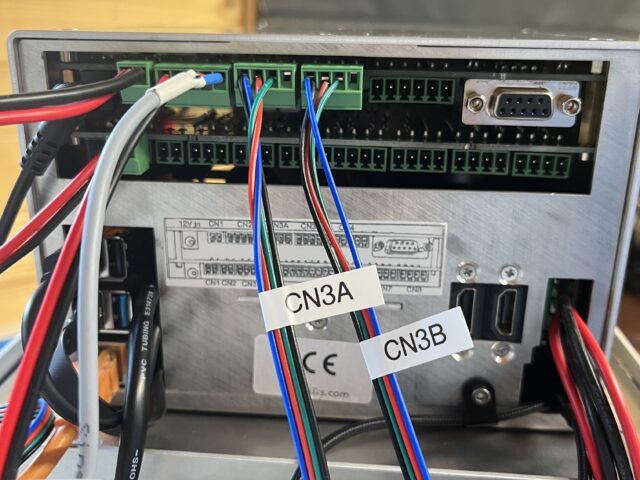
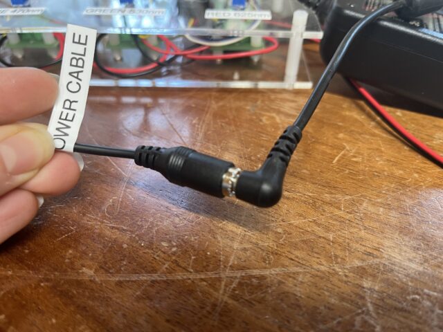
Plug the LED driver into the top box using the two cables with green connectors into CN3A and CN3B on the top box. Connect the LED driver to an external power source with the power cable provided. See images below
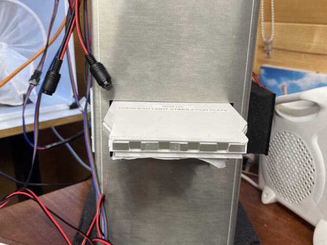
The overhead light stimulation plate slides into the top of the observation chamber. The plate is a tight fit and is held in place by the internal foam in the MWP observation chamber. You will also need to insert the standard light stimulation plate into the bottom of the observation chamber as this also acts as a stand for a multi-well plate or petridish and a diffuser for the IR lighting to provide even lighting. See images below.
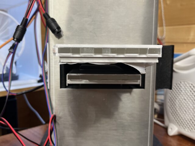
Finally you will need to add the foam door. It has two slots to fit over both the overhead and standard light stimulation plates. The wider hole is for the overhead plate. Once all of this is in place add the LEDs to the end of the overhead light stimulation plate. The LEDs are not central in the LED holder, make sure that the LEDs are the correct way up. The side with the LEDs closest to the foam is the top. This is also indicated by the red cables (i.e. red cable is the top and black is the bottom). See image below
Adjusting LED brightness
The brightness of each individual LED wavelength can be adjusted manually from the LED driver. Using a screwdriver, rotate clockwise to turn the power up and counter-clockwise to reduce the power (and therefore the brightness).
Adjusting the power of two of the LED wavelengths
Zanscript code for operating BGR UV LED
The individual LEDs can be controlled in Zanscript using a few GPO commands. When set to 0 then that LED is off. So for all LEDs to be off you will need the code
SET(GPO3,0)  # red
SET(GPO4,0)  # green
SET(GPO5,0)  # not used
SET(GPO6,0)  # blue
SET(GPO7,0)  # UV
SET(GPO8,0)  # not used
GPO5 and GPO8 are not used by the RGB UV LED driver. For this reason we will not show these two commands for the rest of the example. It is not necessary to include them in the scripting
To turn on the red LED change the GPO3 from 0 to 1 and leave the other LEDs as 0
SET(GPO3,1)    # red
SET(GPO4,0) # green
SET(GPO6,0)    # blue
SET(GPO7,0) # UV
To change to green turn GPO3 back to 0 and GPO4 to 1
SET(GPO3,0)    # red
SET(GPO4,1) # green
SET(GPO6,0)    # blue
SET(GPO7,0) # UV
A demo Zanscript which will turn all of the LED lights on in turn is supplied below. Always ensure you are wearing the correct protective eye ware when working with the UV light as it is extremely bright but you will not perceive it as such. Using the UV LED without the correct safety equipment can cause serious damage to eyes.
Script download: RGB_UV_LED_Demo

